



The shift from brackets and ducts to load-bearing additively manufactured components is forcing engineers to rethink how materials testing campaigns are run. There are key differences in how to approach testing additively manufactured parts of different geometries – a bracket or duct compared to a load-bearing part. Methods like computed tomography can be used to inspect internal lattices, but increasingly in-process monitoring and digital twins need to fit into wider testing and inspection regimes for parts. There are still several barriers in the way of simply incorporating additively manufactured parts into the routine qualification process of an aircraft’s primary structure.
Key testing differences
According to Henning Juknat, global communications leader at NDT company Waygate Technologies, the largest difference between how load-bearing and non-load-bearing parts are tested is the level of defect tolerance and the inspection strategy.
“For a bracket or duct, we are primarily concerned with fit, function and major manufacturing defects. For a load-bearing part, we are more focused on defects, such as porosity, lack of fusion and linear indications. The inspection becomes more conservative because the consequences of failure are much higher,” says Juknat.
Elsewhere, Daniel Sanmartín, technology manager at additive manufacturing NDT specialist Theta Technologies, highlights the necessity for consequence-based risk assessment for load-bearing parts. Whereas an inspection strategy “is usually driven by fit, function, leakage, dimensional conformity and the need to avoid obvious defects“, for a load-carrying or safety-critical component, it “has to demonstrate structural integrity against the full-service envelope” – including static load, fatigue, vibration and thermal cycling, meaning it is application dependent, he says.
Meanwhile, when Roger Wende, sales engineer for VG software at metrology company Hexagon’s Manufacturing Intelligence division, looks at serious load-bearing parts, he and his team are focused on finding internal defects additive manufacturing (AM) processes are prone to.
“AM is different from CNC or sheet metalworking because you’re creating new material, not manipulating existing. And for aerospace and defense you can’t refine the process over a million parts because you might only need one or a dozen,” he says.
Computed tomography
Juknat stresses the merits of computed tomography (CT) for inspecting internal lattices, because it provides a true 3D representation of the structure without destroying the part. Unlike conventional radiography, ultrasound or surface inspection methods, CT “can visualize internal geometries, blocked passages, defects and dimensional analysis within the structure of the component,” he says.
“Where CT outperforms older NDT methods is in its ability to simultaneously assess internal geometry and internal defects in complex AM components that are inaccessible to other techniques,” Juknat adds.
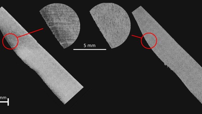
When inspecting lattices, Wende says that CT allows engineers to calculate global deviation against the design file, including visualizing stacked powder on downskin surfaces. Beyond that, he says that they “often need to quantify the deviation between nominal and actual strut thickness, caused by surface roughness and powder accumulation on downskin surfaces“.
“Older NDT methods cannot give the metrology team the accuracy needed to measure these features and verify the part is within tolerance. What’s more, the ability to automate this by importing a measurement template cuts the time an engineer needs to confirm the part is dimensionally correct,” he says.
“Finally, a CT scan gives me both the surface information and material information. I can convert the data to a tetrahedral mesh, which allows a simulation expert to apply the material information and forces to perform finite element analysis,” he adds.
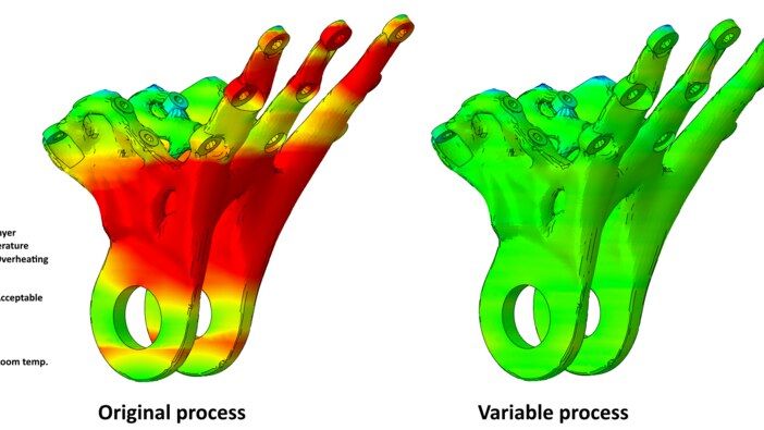
For defect analysis, Wende points out that we are also seeing “big advances from AI and machine learning to add further interpretation to the data and qualify defect types or perform statistical analyses” and thinks vendors and users “will achieve far more in the coming years“.
In Sanmartín’s view, CT is a “powerful” tool for inspecting internal lattices, because it produces a volumetric representation for small parts. For AM users, this means that CT can reveal internal strut geometry, blocked channels, unfused regions, missing features, dimensional deviation, enclosed porosity and surface roughness “in areas that are inaccessible to conventional visual, penetrant or surface-based methods“.
“CT’s advantage is that it can see inside complex geometry without cutting the part open. For lattice-rich AM components, that is a major benefit, because the very design freedom that creates value also makes conventional inspection difficult. CT can also support metrology, reverse comparison to the CAD model and internal failure investigation,” says Sanmartín.
That said, he notes that CT still struggles when the part is large, “because the resolution of the technique degrades with part size” as well as when the part uses dense materials. There are also challenges when the defect size of interest approaches the practical resolution limit for the scan volume, “which is often the case for cracks in lattice structures“, says Sanmartín.
“It is also relatively slow and expensive for production-scale inspection, and interpretation can require specialist expertise,” he adds.
Meanwhile, Marc de Smit, senior additive manufacturing R&D engineer at the Royal Netherlands Aerospace Centre (NLR), observes that although CT currently is perhaps the “only viable way” to inspect AM parts for internal defects, it still struggles compared to traditional NDT methods.
“CT has difficulties with high-density aerospace alloys like Inconel, titanium or cobalt-chrome that attenuate, or absorb, X-rays very strongly,” de Smit says.
“Another limitation of CT scanning is the necessary trade-off between the specimen size and the required resolution. This limits which large parts can be inspected when allowable defect size is very small. Lastly, CT scanning is slow and requires massive data processing and specialized expertise,” he adds.
In-process monitoring
For Sanmartín, although in-process monitoring is essential, it is not a replacement for post-build inspection. In his view, melt-pool sensors, optical monitoring, thermal imaging and re-coater monitoring “provide valuable evidence about process stability and can identify events that correlate with defect formation“, making them “especially useful for trend analysis, process control and early intervention“.
“Most in-process data is indirect. It tells us what happened during the build, not the final part condition after cooling, stress relief, heat treatment, machining, hot isostatic pressing or surface finishing. The part at the end of a process could still have flaws that were not detected, or present, when the part was being made,” he says.
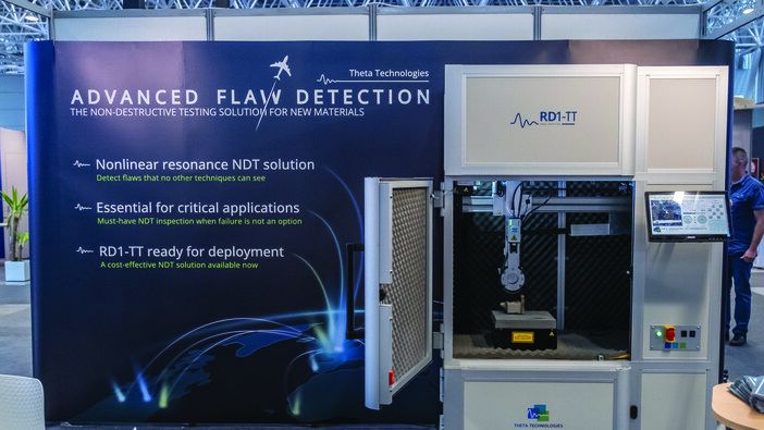
According to Sanmartín, the ideal solution for AM is likely to be a risk management strategy. This would include “process monitoring to control the build and identify volumetric defects, post-build NDT like nonlinear resonance to verify the part, and mechanical testing, to ensure the part is compliant with the requirements“.
De Smit agrees that although in situ process monitoring (ISPM) can become a complementary tool in reducing the NDT effort, it will not replace NDT entirely.
“ISPM can monitor process stability, which can contribute to easier process qualification. Besides that, anomalies can be detected, indicating which parts require NDT. A process failure mode effect analysis can also contribute to describing which defects can be detected with which monitoring tool. In addition, combining different tools can be beneficial,” says de Smit.
“A limitation is that AM machine makers have their own monitoring systems. Standardization is important for acceptance. Another challenge is that variations in the AM process for complex parts cause variations in properties and noise, which makes defect detection more difficult,” he adds.
In the future, Juknat envisages a combination of both approaches – with in-process monitoring “reducing inspection time and increasing confidence“, while CT and other NDT methods “continue to provide verification of the finished component“.
Digital twins
In Sanmartín’s view, the problem with coupon testing is that to obtain good results, the coupons need to be machined and polished. This reduces the surface roughness of AM parts.
“Digital twins can reduce the number of coupons in certain contexts, but for primary structure this is still partly aspirational. The reason is not that modeling is weak; it is that the model must be trusted across material, machine, process window, build orientation, post-processing route, geometry and service environment,” he says.
“An example of this is heat treatment, which can be used to control and modify the microstructure of a part and radically change its material properties,” he adds.
In contrast to subtractive manufacturing, Sanmartín notes that, in additive techniques, the material is “actually created during the build, and material properties vary based on the local conditions around the melt pool“. This means that a digital twin model based on a simple material definition is likely to perform “very differently to a real part, in which the material properties around thin walls may be very different from dense sections“.
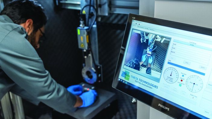
“Where we think we can add value is by comparing the digital twin model outputs with the measured acoustic signatures on actual complex parts to verify if the material property assumptions are correct, providing the validation and feedback that the digital twins need,” he says.
Meanwhile, de Smit observes that, to “cut a substantial number of coupons by information gathered through digital twins“, engineers would require a system “that captures all of the process physics, from feedstock to post-processing, that influence the final part quality and performance“.
Largest hurdles
For Dr Olaf Günnewig, head of business development at CT and NDT system supplier Diondo, the single largest hurdle in the way of qualifying additive manufacturing is confidence in the repeatability of material properties and defect populations.
“Primary structures require predictable, statistically robust performance, but laser powder bed fusion processes can introduce variability in microstructure, defects and mechanical behavior across builds, machines and parameter sets, making it challenging to establish reliable design allowables and qualification frameworks comparable to conventional manufacturing,” he says.
Günnewig stresses that laser powder bed fusion (LPBF) is a sensitive process with a complex multi-parameter interaction, meaning that “even slight deviations can shift the process from stable melting to defects like lack of fusion“.
“One of the biggest hurdles is fatigue and damage tolerance. Whereas the static strength of many AM parts is very good, fatigue performance can be challenging as small defects in the AM component, including pores, lack of fusion, roughness or residual stress, can influence its fatigue life,” he says.
Because routine qualification of AM components is still difficult, Günnewig notes that the aviation industry generally adopts “a combination of process control, qualification strategies and digital monitoring, rather than trying to eliminate variability entirely“.
Meanwhile, Wende points out that the AM ecosystem, and early adopters in industries like aerospace, have matured a great deal in the past four years, and that the biggest barriers are now largely non-technical.
“There hasn’t been a clear, achievable path from an OEM’s engineering qualification to civil flight certification, which has prevented more optimal AM parts from replacing legacy components and confined adoption to a small number of new aircraft programs,” Wende says.
“In defense, adoption is now rapid and we will see substantial use of additive’s design and manufacturing freedom in new concepts,” he says.
Frozen process
LPBF is a sensitive process with complex, multi-parameter interactions. Günnewig says, “Controlling the full digital and physical thread from powder to finished part is important.
“Any change in powder, machine state, parameters, build orientation, heat treatment or inspection route can change the defect population and microstructure.
“Therefore, the process must be locked with a frozen process, monitored, documented and requalified whenever something changes. To ensure a consistency of behavior, the future must be ‘hybrid’, [with] qualified processes, targeted coupons, component testing, high-speed CT, in-process monitoring and digital twins used together to ensure build certification confidence.”
Elsewhere, Wende believes the industry can now be “confident in the design aspects” of AM parts, and he stresses that future considerations will be focused on the manufacturing process. “There are so many things that could go wrong, so you need to understand and control all of them as part of your quality assurance,” he says.
“You need to understand and control the environment, because changes in moisture or temperature, for example, are well documented for affecting porosity or curing and bonding. And you need to use data – unlike milling a part, even small changes across many process parameters can shift the outcome, so even relatively modest production volumes benefit from sophisticated statistical or AI-based process control,” he adds.
